Blog #2 The Rocket Progress
- mtaroua
- Oct 2, 2021
- 3 min read
Updated: Oct 2, 2021
During this year, the Cougar Rocket team will be working on designing and building a modular motor mount (MMM) that consists of 4 main circular disks, the goal is to hold the fins while keeping the motor of the rocket inside the airframe centerline and stable. The rocket team will work on a strategy that will lead to having the fins held into the MMM, by reducing the number of bolts used. This will result in saving time during the reassembly process. The goal of the project is for the MMM to be lighter than the previous design, satisfy the criteria set by the client (AIAA), reduce the number of bolts to be able to replace the fins easily and faster, and finally to find a suitable material that works best for the project and will lead to a more consistent design and increase the modularity of the MMM.
After meeting with the American Institution of Aeronautics and Astronautics’ lead team and gathering the information needed, the Cougar Rocket team has agreed on multiple different preliminary designs for the new MMM but faced many technical issues along the way. The technical issues that our team has faced were the inconsistency with other sub-teams that were unable to provide the information needed to start the 3D design due to their indecision of choosing the motor that will be used in Zenith. Since the motor and MMM rely on each other, the delay of this information caused our team to slow our progress on the 3D design, and shifted the team’s attention to other tasks. Another technical issue that our team has faced is the precision behind the mechanism that will be used on the MMM. Currently, the Rocket Team is conducting research to know if the designs can be made by the on-campus machinist, or will we outsource the machining of the components.
The team has already agreed on multiple analyses that will be conducted on the MMM once the prototype is ready. A Structural mechanics Finite Element Analysis (FEA) will perform a simulation of the motor thrust of 8034 N on the thrust plate during take-off. The thrust plate must prevent the motor from flying forward in the motor tube while withstanding the force of 8034 N. While the FEA simulation is useful for approximating stress values, in order to truly validate the design, the team will utilize a load cell to build the strain gauge and a heat flux sensor as a validation method to test the prototype at maximum thrust values and high-temperature conditions. The team will also do a comparative analysis on aluminum and carbon fiber to evaluate the performance of chosen material. The team has also decided that a Heat transfer FEA will be performed to ensure the integrity of the material of choice based on the structural mechanics analysis.

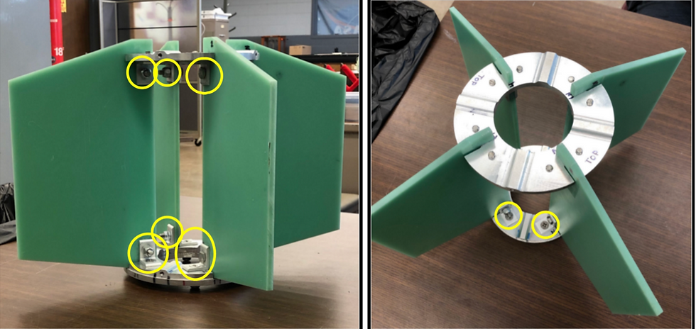
The figures show multiple preliminary designs that the team has been working on during the past month before starting the 3D CAD design. The first design displayed in Fig. 2 is that of the “Encased” MMM design that has the fins secured to the MMM by four springs that force the top and bottom centering rings to the fins. In this design, there are small divots located in both the top and bottom centering rings that the fins would be fitted into. To match these divots, the fins have bulges of the same size. When placed within these divots, the fins will not be able to move laterally along the ring. The divots working in conjunction with the springs allow for an MMM design that reduces the number of overall parts while continuing to innovate.
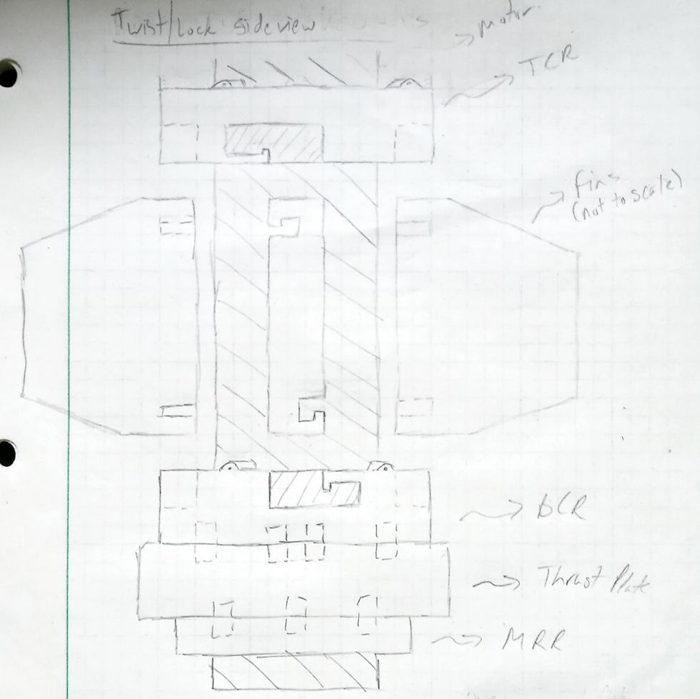
Fig. 3 showcases the “Twist/Lock” MMM design that redesigns the centering rings to be able to easily replace damaged fins by simply twisting the MMM. The fins will be modified to have small cutouts that are mirrored within the bottom and top centering rings. These cutouts when twisted will lock the centering rings and fins together without the use of bolts for the upper design.
BCR: Bottom Centering Ring
TCR: Top Centering Ring
MRR: Motor Retaining Ring


Comments